Лъчисти стоманени таванни панели: Разлика между версии
Направо към навигацията
Направо към търсенето
| Ред 19: | Ред 19: | ||
Тази статия описва проектиране на отоплителни системи със лъчисти таванни панели. | Тази статия описва проектиране на отоплителни системи със лъчисти таванни панели. | ||
== | ==МОДУЛИ И ПРОГРАМНА КОНФИГУРАЦИЯn== | ||
* '''InstalSystem 5''' | * Пакет '''InstalSystem 5''' със следния модул: | ||
**''' | **'''Лъчисти отоплителни/охладителни системи със стенни/таванни панели''' | ||
==Inital state== | ==Inital state== | ||
Версия от 04:29, 22 ноември 2017
| Продукт | InstalSystem 5 |
| Вид статия | DESIGN APPLICATION |
| Актуално съдържание за версия | IS 5.0 Beta 33 |
ОБХВАТ НА УРОКА
Тази статия описва проектиране на отоплителни системи със лъчисти таванни панели.
МОДУЛИ И ПРОГРАМНА КОНФИГУРАЦИЯn
- Пакет InstalSystem 5 със следния модул:
- Лъчисти отоплителни/охладителни системи със стенни/таванни панели
Inital state
- Building structure has been created (storeys, rooms).
За повече информация, моля вижте: Preparation of building structure. - Drawing with plan of storeys has been loaded.
За повече информация, моля вижте: Import files. - Design heat loads of rooms have been determined for heating using available methods:
- indicatively in units of W/m2
За повече информация, моля вижте: Общи данни-Сграда и околности - manually, separately for each room
- detailed calculation
За повече информация, моля вижте: Calculation of design heat load of rooms
- indicatively in units of W/m2
Steps to perform
Load catalogues and set default data for the project
Общи данни window
| Project files
|
Initial state, isproj System with radiant ceiling panels in a public building, isproj |
| Designed with | InstalSystem 5 Rev. Beta 33 |
| Required modules | InstalSystem basis Radiant heating system 5 Radiant panel systems 5 |
| Project range | Radiant heating |
| Used catalogues |
Basic radiant systems |
| Type of building | commercial building with basement 2-storey |
| Building structure | Ground floor base drawing, dwg First floor base drawing, dwg |
| Drawings range | Plan drawings |
| Prepared by |  www.instalsoft.com |
| Legal disclaimer | Copy all or fragments allowed |
| Calculation results | Complete range of calculation results, xls Complete range of available printouts, pdf Heating calculation results, pdf Bill of materials, pdf |
| Drawing results | Ground floor, dwg |
- Tab - Изчислителни раздели (модули) - specify scope of project: Отоплителни системи / Охладителни системи.
- Tab - Управление на етажи – verify and specify basic parameters:
- Етажна височина
- Default distance between ceiling and distribution pipe-runs to radiant panel system (ΔHуч.пан.)
- Default distance between ceiling and radiant panels by entering the value in field (Дебелина на окачен таван)
- Tab - Каталози – load product catalogues required for the project.
- Tab - Термални системи / Източници – verify parameters: Използване на източник подразбиране and supply temperature (θs,О).
- Tab - Термални системи / Разпределителна система / Виртуални връзки на лъчисти системи - select option Позволи системи без колектори.
- Tab - Термални системи / Разпределителна система / Pipes and insulation - types and default data – specify default pipe and insulation types, verify temperatures in fields Околна температура по подразбиране на участък.
- Tab - Лъчисти системи / Панели – specify default types and sizes of radiant panels and correct the minimum (Δθ мин.) and maximum (Δθ макс.) values of permissible temperature drop of the medium. Optimum value will be determined within the interval for every radiant panel in order to attain the required output.
За повече информация, моля вижте: General data
Edit installation - radiant ceiling panels
Insert radiant panels and edit graphically
Verify the arrangement of radiant panels, i.e. distances between panels, distances to top slab and external walls, with manufacturer's guidelines.
- Select Лъчисти тавани.
- Using the АВТО mode settings specify the desired distance between radiant panel and external wall.
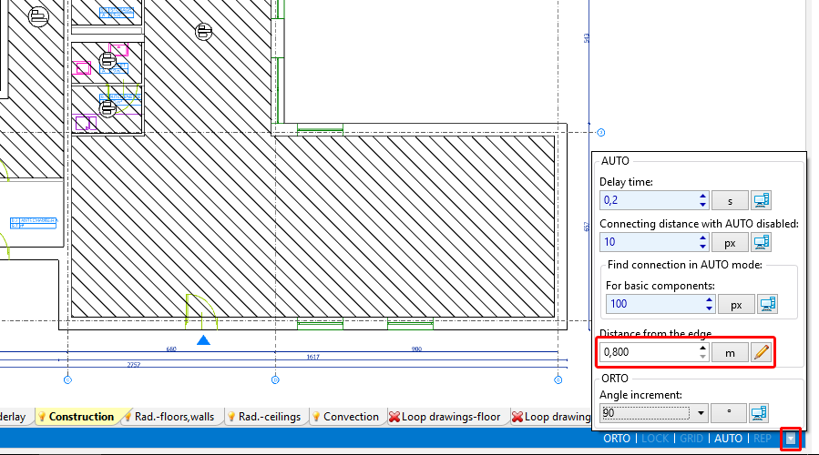
1. Radiant ceiling panel - Insert the radiant panel using the icon Тавенен панел in group Лъчисто
- Adjust the length of the radiant panel to the dimensions of the room by dragging terminal points of the panel and expanding it.
The length of the panel in the drawing does not have to correspond to the real length of a single panel. Based on the required length, the program will assemble a set of base panels and connection headers connected in series with its total length coresponding to the required length. - Insert subsequent radiant panels by clicking again the Тавенен панел icon or by copying panels already inserted. When necessary modify the settings of the АВТО mode.

Initial calculations - diagnostics of the heat demand coverage in room
- Run radiant heating calculations by clicking the
 icon in the Изчисления group.
 - Verify the heat demand coverage in room in:
- the Диагностики window by viewing the list of warnings
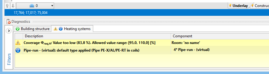
2. Verification of heat demand coverage in room in the Диагностики window - the Резултати window on tabs - Количество на помещения - отопление
- hint in bubble displayed upon positioning the cursor within the panel area
- the Диагностики window by viewing the list of warnings


Modify data to adjust the attained output to the required output
- Adjust the following data and parameters:
- supply temperature in the general data of the source (θs,О).
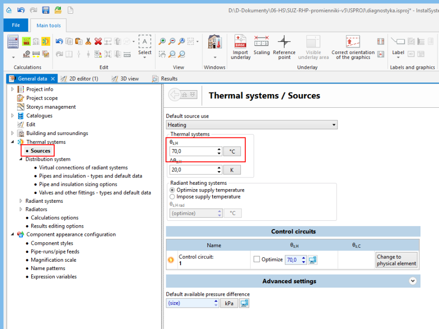
3. Adjustment of supply temperature in Общи данни - required drop of temperature of the medium in the radiant panel (Δθнеоб.,О).
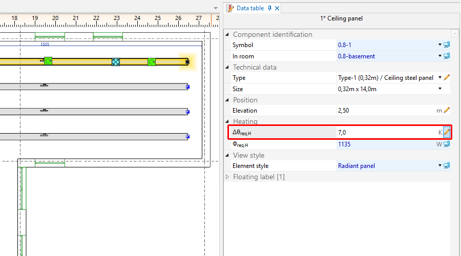
4. Adjustment of temperature drop of medium in radiant panel (Δθwym,H) - number/size of radiant panels
- supply temperature in the general data of the source (θs,О).
- Recalculate the project – verify the effect of the changes made on the attained heating output.


Edit installation - append drawings with the medium distribution system
- Upon attaining satisfactory results for the coverage of heat demand in rooms, insert the other components of the system (source, pipe-runs, fittings) and connect them to the radiant panels.
Make complete calculations including system balancing and bill of materials
- Make calculations for radiant heating by clicking the icon in the Изчисления group.
- Verify the diagnostics and calculation results, in particular:
- Required source parameters - Резултати window – Резултати от отопление/Общи резултати от отопление tab
- Flow balance – Резултати window – Кръгове tab
- Bill of materials - Резултати window – Количествена сметка на материали - отопление / охлаждане tab
За повече информация, моля вижте: Calculations and diagnostics
Verify visually arrangement of the system in 3D view
- Open the 3D изглед window and check system arrangement. If necessary, modify the elevations of the components and positions of connection points. Recalculate the project if corrections were made.
За повече информация, моля вижте: Verification of the correctness of installation structure
5. 3D view

Prepare drawings for printing/export
- Verify the drawing style of the panel in 2D and 3D views and the level of detail of information provided in the label. Configuration is given in the Общи данни window.

- Insert and set labels of other system components (source, pipe-runs, fittings).
За повече информация, моля вижте: Preparation of drawings for export/printing
Export / print results and drawings
За повече информация, моля вижте: Export / print results and drawings