Автоматично създаване на изгледи
| Продукт | InstalSystem 5 |
| Вид статия | ФУНКЦИОНАЛНОСТИ |
| Актуално съдържание за версия | REVISION Rev. 17.1 |
Описание
This article describes the method of creating automatic schematic views of installations based on an installation model of Приложение: Отоплителни системи or Приложение: Охладителни системи type with an option to manually edit these views, insert fittings and regenerate the view at any time.
Schematic views of installations are generated in the 2D editor using Начална точка (отоплителни инсталации) components.
This functionality is currently under development and was included in the BETA version.
Местоположение в програмата
Icons of components and of functions for controlling the automatic generation of schematic views are available in the 2D редактор window on the Главни ленти с инструменти bar in the Схематичен изглед section within the Конвекция, Лъчисти подове, стени, Лъчисти тавани editing scopes.

The generated Тип на лист: Схематичен изглед components are at the bottom of the sheet list.

Examples of use
Провери връзки
Checking the correctness of connections using the Провери връзки operation or by pressing Shift+F2 is necessary for the proper generation of the schematic view. The project file can include messages on error relevance, but these messages cannot relate to connection errors.
Presentation of the basic components and functions for controlling automatic generation of schematic views
Начална точка (отоплителни инсталации)
This is the starting point in the installation from which the schematic view is generated. It has to be assigned a unique symbol. Many Начална точка (отоплителни инсталации) components can be inserted, and each of them generates a separate Тип на лист: Схематичен изглед ![]()
The Начална точка (отоплителни инсталации) can be placed on:
- Генератор на топлина и студ
- Вертикален клон
- Двойка участъци
- Двоен колектор
- Плоска станция
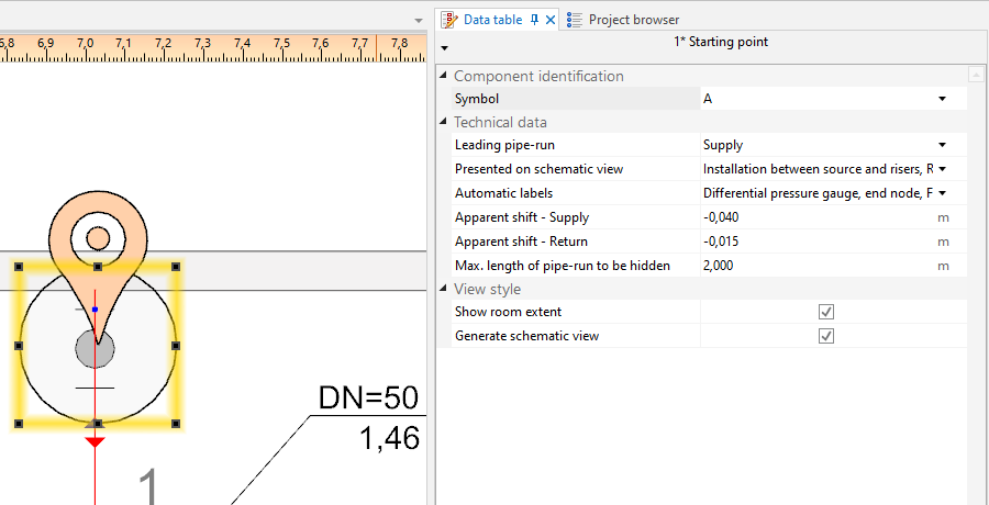
3. Начална точка (отоплителни инсталации)

- Главен участък
Indication of the pipe-run which has a priority when generating a schematic view. This is important when generating an asymmetrical installation (supply and return pipe-runs arranged along different routes). All junctions (tees, crosspieces) are also marked on leading pipe-runs.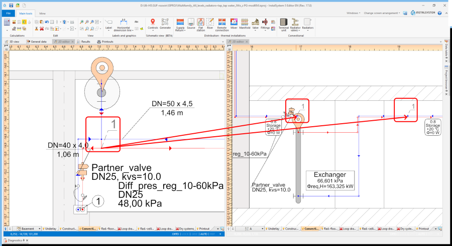
4. Junction (tee)
The scope can be reduced:- Инсталация между генератор на топлина и вертикални водопроводни клонове - generates the schematic view from the indicated point to risers, excluding the risers
- Вертикални клонове - generates the schematic view from the indicated point to risers, including the risers
- Монтаж за вертикални клонове - generates the schematic view from the indicated point beyond the risers to terminal units. If an installation includes stations, the schematic view is terminated at the station, if the installation includes manifolds, the schematic view is terminated at the manifold.
- Монтаж зад плоски станции - generates the schematic view from the indicated point to the station including the installation beyond the station (checkbox Монтаж за вертикални клонове must be checked)
- Монтаж зад колектор - generates the schematic view beyond the manifolds (checkbox Монтаж за вертикални клонове must be checked)
- Control over automatic labelling.
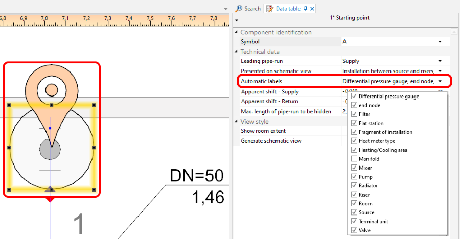
5. Schematic view - labels control - Фантомно изместване
Enables display in the schematic view of pipe-runs that are on the same level (elevation). Does not affect the elevation of the pipe-run in the model.- Positive value - this value is added to the elevation of the supply pipe-run in the schematic view.
- Negative value - this value is subtracted from the elevation of the supply pipe-run in the schematic view.
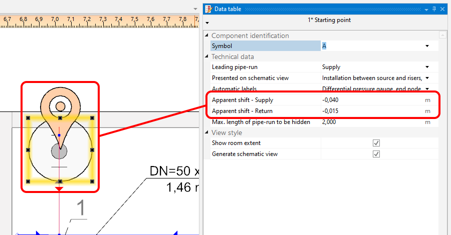
6. Фантомно изместване 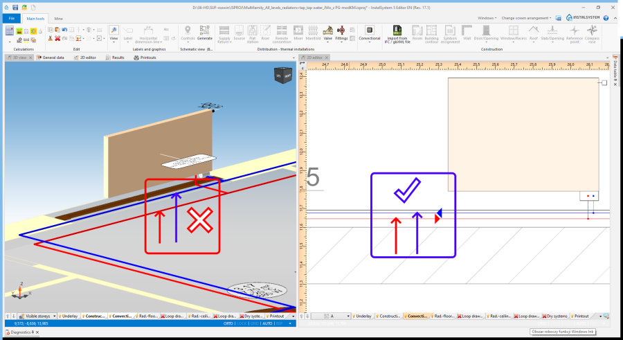
7. Фантомно изместване - supply and return
- Покажи степен на помещение
Marked rooms and their labels.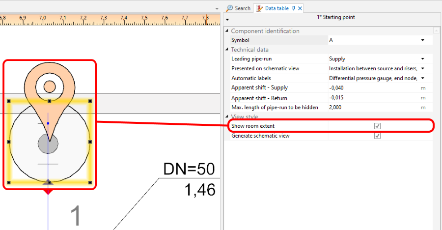
8. Покажи степен на помещение 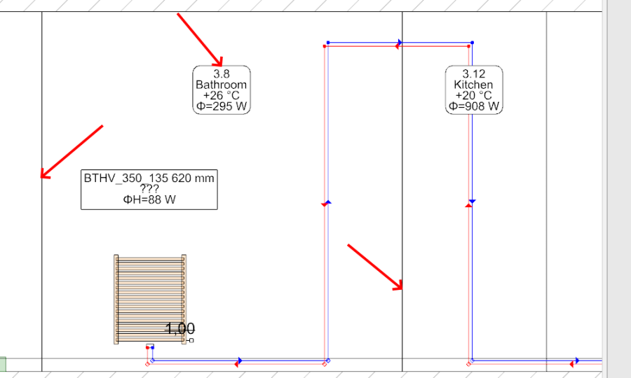
9. Покажи степен на помещение - room marked in the schematic view - Създай схематични изгледи
Unchecking this option disables the generation of the schematic view during subsequent generations, e.g. new settings for the automatic schematic view control functions will not be taken into account. However, disabling this option does not affect installation components. The installation components are refreshed automatically, i.e. the number of installation components in the model always corresponds to the number of installation components in the schematic view. If this option is disabled, a padlock icon is shown in the sheet selection list .
.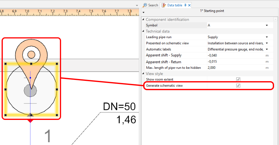
10. Създай схематични изгледи


Контролна точка
Enables controlling the direction of generation of individual pipe feeds on the schematic view and modification of the leading route. It must be placed on the leading pipe-run. The control point changes the course of the schematic view starting from the junction beyond which it was inserted. Many Контролна точка components can be inserted and they can be placed in a Тип на лист: Схематичен изглед or a Тип на лист: Изглед в план.

- Посока.
Specifies, for instance, whether a part of an installation (e.g.: Вертикален клон) is to be treated as placed to the right or to the left of the Генератор на топлина и студ. Similarly, one can decide whether a part of the installation is to the right or to the left of a Вертикален клон. The video shows how two risers are moved in the schematic view to the left of the source.
- Прекъсни връзката със схематичен изглед.
Enables modifying the leading route in the schematic view. The video shows how the leading route is changed in such a way that the critical route is presented as the first one.
Крайна точка на схематичен изглед
The schematic view of the part of installation that is beyond the Крайна точка на схематичен изглед is not generated. This part of installation is represented by a Фрагмент на инсталация. The Крайна точка на схематичен изглед must have a unique symbol assigned.
The video shows how a riser is removed from the schematic view.
Parts of installation that are not subject to automatic generation of schematic views
- Installations with ceiling panels.
- Installations with wall panels.
These parts are automatically terminated with a Фрагмент на инсталация.
Manual editing and configuring
- Inserting independent components.
The following components can be placed in a Тип на лист: Схематичен изглед:- additional labels (e.g.: pipe-run labels). The positions of the inserted labels can also be changed - these positions are maintained after the schematic view is regenerated,
- valves,
- fittings placed on pipe-runs,
- radiator fittings.
Additional information
- Project file created with InstalSystem 4 which includes a Тип на лист: Схематичен изглед loaded into InstalSystem 5.
Such a sheet is not converted into a Тип на лист: Схематичен изглед of InstalSystem 5 and it is removed when loading - appropriate diagnostic message is displayed.