Проектиране на инсталации с плоски станции: Разлика между версии
Редакция без резюме |
Редакция без резюме |
||
| Ред 205: | Ред 205: | ||
<!-- Do not write text below this tag --> | <!-- Do not write text below this tag --> | ||
<br class="iwlinks"/>[[pl:Projektowanie instalacji z zastosowaniem stacji mieszkaniowych|Projektowanie instalacji z zastosowaniem stacji mieszkaniowych]] | <br class="iwlinks"/>[[pl:Projektowanie instalacji z zastosowaniem stacji mieszkaniowych|Projektowanie instalacji z zastosowaniem stacji mieszkaniowych]][[en:Designing installations with flat stations|Designing installations with flat stations]][[zh-cn:采用户用换热机组作为热源的供热系统以及给水系统的设计|采用户用换热机组作为热源的供热系统以及给水系统的设计]] | ||
Версия от 23:54, 12 февруари 2021
| Продукт | InstalSystem 5 |
| Вид статия | Софтуерни приложения |
| Актуално съдържание за версия | GOLD rev. 17.0 |
Обхват на урока
Статията показва как да проектирате инсталации с помощта на плоски станции. Последното може да се превърне в точка за свързване на отопление и водоснабдяване на апартаменти.
Асинхронизирането на флуида за отопление с битова гореща вода се взема предвид при оразмеряване на захранващата система на плоска станция. Типът и размерът на плоската станция се избират от потребителя, като междувременно програмата диагностицира дали дадена плоска станция е в състояние да достави достатъчно мощност към отоплителната система, към която е свързана, и за декларирани / изчислени параметри за битова гореща вода.
Modules and program configuration
- InstalSystem 5 package with the following modules:
- Плоски станции
- Отоплителни системи
and as an option: - Лъчисти системи - if the station is supposed to supply an apartment radiant system with heating medium
- Питейни-битови водни системи - if calculations for the flat station and the supply system should include flow rate of a sanitary system designed with InstalSystem 5
- Плоски станции
Initial state
The project contains a building structure (storeys, rooms) and a storey plan drawing.
Room heat load values for heating has been declared.
За повече информация, моля вижте: Preparation of building structure
За повече информация, моля вижте: Import underlay files
Steps to perform - Scenario I - valueДебит на топла вода declared manually
Defining catalogues and general data
| Project files
|
Initial state, isproj Installation containing flat stations in a multifamily building, isproj |
| Designed with | InstalSystem 5 Rev. 17.0 |
| Required modules | Flat stations Heating systems Radiant loop systems Radiators sizing |
| Project range | heating systems, sanitary systems |
| Used catalogues |
Basic radiant systems |
| Type of building | residential building present 4-storey |
| Building structure | Underlay basement, dwg Underlay groundfloor, dwg Underlay floor, dwg Underlay attic, dwg |
| Drawings range | Plan views |
| Prepared by |  www.instalsoft.com |
| Legal disclaimer | Possibility to copy the whole projects or its fragments |
| Calculation results | Full calculation results, xls Full printout, pdf General heating results, pdf General water supply system results, pdf Bill of materials, pdf |
| Drawing results | Basement, dwg Groundfloor, dwg Floor, dwg Basement, pdf Ground floor, pdf Floor, pdf |
Общи данни window
- Каталози tab – read the catalogue containing flat stations.
- Термални системи / Плоски станции tab - complete Вид and other general data, in particular:
- V̇ТВ Апартамент (Дебит на топла вода),
- ΔθТВ (Степен на нагряване на топла вода)
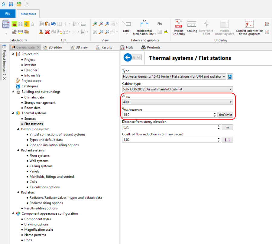
1. Общи данни

Editing installation
Inserting and graphic editing of flat stations
- Choose the Конвекция/Лъчисти подове, стени editing scope.
- Insert a flat station using the Плоска станция button. Turn to a chosen angle, if needed.
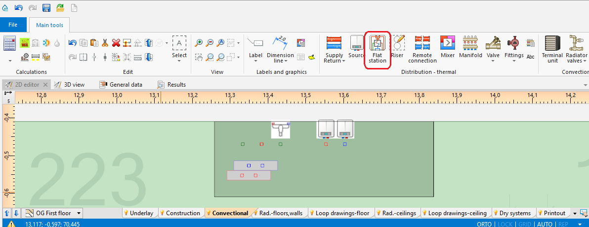
2. Inserting Плоски станции - Конвекция/Лъчисти подове, стени editing scope

Verification and completion of installation data
- In the window Таблица с данни, verify data of eachПлоска станция element in scope of:
- Вид,
- Разстояние от кота готов под,
- V̇ТВ Апартамент,
- ΔθТВ (ATTENTION! The input temperature of domestic hot water feeding the flat station results from properties of a given producer's heat exchanger, and it usually amounts to 10°C),
- accessories and their data.
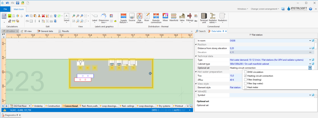
3. EditingПлоски станции - Data table

Connecting flat stations
- Connect heating system medium feed and return on the primary side to the place indicated by the symbol
 . За повече информация, моля вижте: Connecting storeys with the "Stack" element
 - Connect radiant system feed and return to the place indicated by the symbol
 , created according to the following article:Designing of radiant heating floor and wall installation.
 - Connect radiator heating system feed and return to the place indicated by the symbol
 , created according to the following article: Designing heating systems with convective radiators.


(optional) Copying Плоска станция elements with/without apartment systems on other storeys
Installation copying
- Select Плоска станция and/or chosen system elements.
- Copy selected elements on neighbouring storeys with the function Копирай избрани елементи на етажа оггоре/Копирай избрани елементи на етажа отдолу.
Creating a copy of a whole storey
Общи данни window
- Сграда и околности / Управление на етажи tab - select a storey and press Копирай.
Verification of installation structure correctness
- Verify correctness of the installation structure with the Провери връзки function (shortcut: Shift + F2).
- Verify correctness of the installation structure and detect collisions using 3D изглед.
За повече информация, моля вижте: Verification of the correctness of installation structure
Calculation performance and verification
- Perform full calculation by clicking the calculator icon
 situated in the Изчисления section on the toolbar.
 - Verify diagnostics and calculation results, in particular:
- flow rate on the heat exchanger primary side - if it exceeds the admissible value, such an error may occur:

4. Heat exchanger out of range.
in such a case, correct computational data (θs,О and/or V̇ТВ Апартамент i/lub ΔθТВ) or choose a different exchanger dimension manually,
- flow rate on the heat exchanger primary side - if it exceeds the admissible value, such an error may occur:


- required total output,
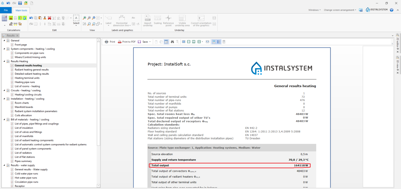
5. Total output required. - (in selected versions) the required buffer tank capacity,
- list of flat station materials.
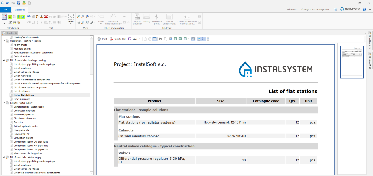
6. List of flat stations.
- required total output,


За повече информация, моля вижте: Calculations and diagnostics
Printout/export of results
- Print/export drawings.
- Print/export tables.
За повече информация, моля вижте: Export / print results and drawings
Steps to perform - Scenario II - Дебит на топла вода value calculated by the Питейни-битови водни системи module
Defining catalogues and general data
Общи данни window
- Zakres projektu tab - checkВодоснабдителни инсталации.
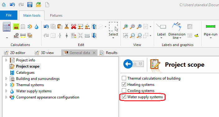
7. Declarated project scope. - Каталози tab – read the catalogue containing flat stations.
- Термални системи / Плоски станции tab - complete Вид and other general data, in particular:
- V̇ТВ Апартамент (Дебит на топла вода),
- ΔθТВ (Степен на нагряване на топла вода)
- Начин на дефиниране: Дебит на топла вода: "Определен от Потребителя" or "Съгл. изчис. на модула: Водоснабдителни инсталации"
- for "Определен от Потребителя" - the V̇ТВ Апартамент (Дебит на топла вода) value is declared manually in the field below and in theТаблица с данни window after inserting stations on the drawing
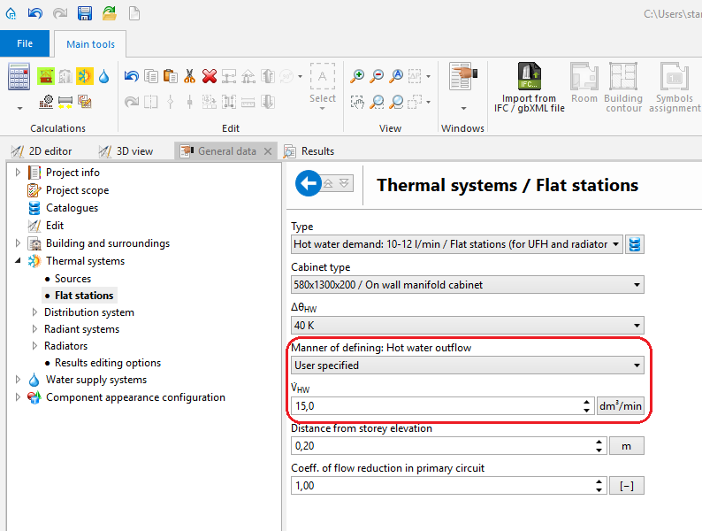
8. User-specified hot water outflow - for "Съгл. изчис. на модула: Водоснабдителни инсталации" - the V̇ТВ Апартамент (Дебит на топла вода) value will be calculated on the basis of the flat station connected sanitary system flow rate, according to the calculation norm selected in the Питейни-битови водни системи module. Additionally, it is possible to choose the method of dimensioning the water supply system (Оразмеряване на основна мрежа съгл. : "TU Dresden" or "DIN 1988-300").
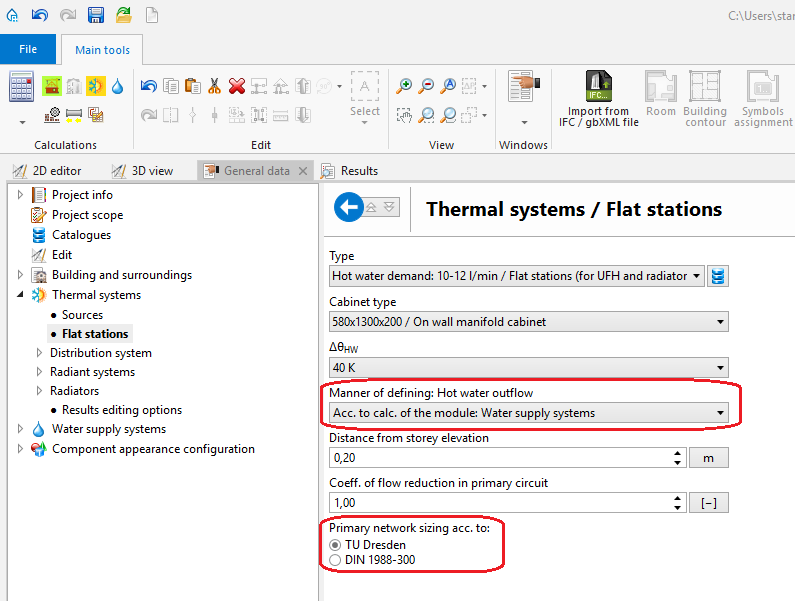
9. Declaring manner of defining hot water outflow
- for "Определен от Потребителя" - the V̇ТВ Апартамент (Дебит на топла вода) value is declared manually in the field below and in theТаблица с данни window after inserting stations on the drawing


Editing installation
Inserting and graphic editing of flat stations
- Choose the Water supply editing scope.
- Insert the flat station using the Плоска станция icon.
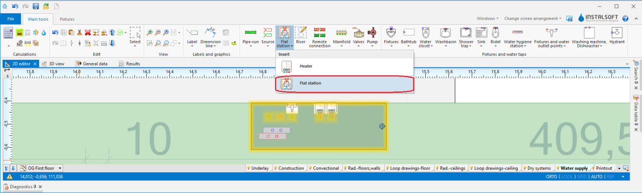
10. Inserting Плоски станции - Water supply

Verification and completion of installation data
- In Таблица с данни, verify data of each Плоска станция element in scope of:
- Вид,
- Разстояние от кота готов под,
- V̇ТВ Апартамент (ATTENTION! If, in the Общи данни window, the Съгл. изчис. на модула: Водоснабдителни инсталации option is selected, this value is calculated automatically),
- ΔθТВ (ATTENTION! The input temperature of domestic hot water feeding the flat station results from properties of a given producer's heat exchanger, and it usually amounts to 10°C),
- accessories and their data .
11. Editing Плоски станции - Data table
Connecting flat stations
- Connect heating system medium feed and return on the primary side to the place indicated by the symbol . За повече информация, моля вижте: Connecting storeys with the "Stack" element
- Connect radiant system feed and return to the place indicated by the symbol , created according to the following article:Designing of radiant heating floor and wall installation.
- Connect radiator heating system feed and return to the place indicated by the symbol , created according to the following article: Designing heating systems with convective radiators
- Connect medium inflow for the sanitary system as well as sanitary system feed and return to the place indicated by the symbol
 , created according to the following article:Designing of water supply system installation.

Verification of installation structure correctness
Steps to perform just like in Scenario I - Дебит на топла вода value declared manually.
Calculation performance and verification
Steps to perform just like in Scenario I - Дебит на топла вода value declared manually.
Printout/export of results
Steps to perform just like in Scenario I - Дебит на топла вода value declared manually.