Автоматично присъединяване на терминални прибори
Направо към навигацията
Направо към търсенето
| Продукт | InstalSystem 5 |
| Вид статия | FUNCTION AND TOOL |
| Актуално съдържание за версия | BETA REV. 0.0.B21 |
Description
The Отоплително-охлаждаща повърхност component (floors and ceilings) can be appended with drawings of loops. Drawings generated automatically by the program are refreshed each time the project is recalculated. It is possible to modify or append them and loops can be drawn manually. Manual editing is recommended at the final stage of design.
Location in the program
- Общи данни - automatic generation of loops can be enabled for all components by selecting the Създай чертежи със сключени вериги (кръгове) checkbox.
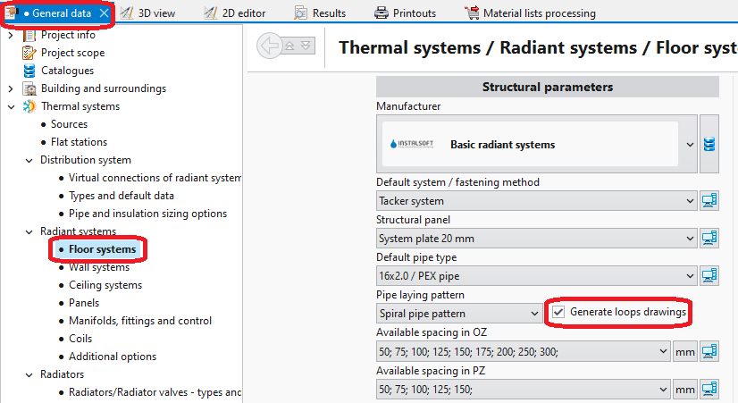
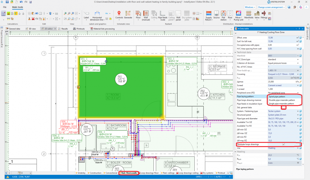
1. Loops drawings - General data - Таблица с данни for component Подова отоплителна/охладителна зона, when working in the Лъчисти подове, стени/Лъчисти тавани editing range, enables:
- automatic generation of loops by selecting the Създай чертежи със сключени вериги (кръгове) checkbox; loop generation can be disabled here for a selected component when this checkbox is selected in Общи данни,
- selection of pipe laying pattern.
2. Pipe laying pattern
- The RHC кръг tool available in Главни ленти с инструменти, when working in the Чертежи на пръстен - под/Чертежи на пръстен - таван editing range, enables manual drawing of loops. Use of this tool is recommended with the МРЕЖА mode enabled.

3.Loop drawings - Graphical editing


Example of use
Automatic generation of loop drawings
- Enable generation of loop drawings in general data or for selected components.
- Calculate the project
 . Upon calculating the project, loop drawings will be generated automatically.
 - Change direction of loop arrangement (option).
After selecting Отоплително-охлаждаща повърхност hotpoints of loop laying direction become available , and in the case of Еднотръбен меандриращ шаблон/Двутръбен меандриращ шаблон a pointer is also available
  for indicating the side along which meandering is to be done. To display the effect of changing the loop laying direction and of indicating other side, the file must be recalculated.
Manual editing of loop drawings
- Disable generation of loop drawings for selected components Отоплително-охлаждаща повърхност.
Attention! Clearing the Създай чертежи със сключени вериги (кръгове) option does not remove existing drawings of loops, it only freezes them in their current state and enables manual editing or deleting thereof. To completely remove loop drawings double left click the loop and select Delete selected components. - Enable the МРЕЖА mode which helps in correcting or manual drawing of loops. Grid nodes are arranged at the minimum distance allowable for the selected pipe laying pattern. Colours of grid nodes are repeated for the current pipe spacing, which facilitates drawing with the use of that spacing. The grid can be arranged parallel to selected edge of component Подова отоплителна/охладителна зона by positioning on that edge the blue hot-point
 . It becomes available when component Подова отоплителна/охладителна зона is selected.
 - Correct/draw manually selected segments of loop.
- The loop drawn must be contained completely within the Heating/cooling surface component and must terminate at its edge.
Ręczna edycja rysunków pętli w systemach suchych z wstawionymi płytami prowadzącymi
- Ręczna edycja pętli jest jedynym sposobem uzyskania poprawnych pętli w systemach opartych na elementach typu Суха система плоча .
- W przypadku podłogowych systemów suchych z ułożonymi w programie elementami katalogowymi Суха система плоча, rolę siatki pełnią charakterystyczne punkty płyt.
- Dla systemów suchych z wstawionymi płytami prowadzącymi zalecane jest użycie funkcji "чертожна дължина на пръстен".
За повече информация, моля вижте:How to include the drawing loop lenght in the calculations?
Additional information
- Graphic style - in order to improve the legibility of loop printouts, one can:
- select manner of loop display where loops differ in colour and pipe feeds are of the same colour as the corresponding loops
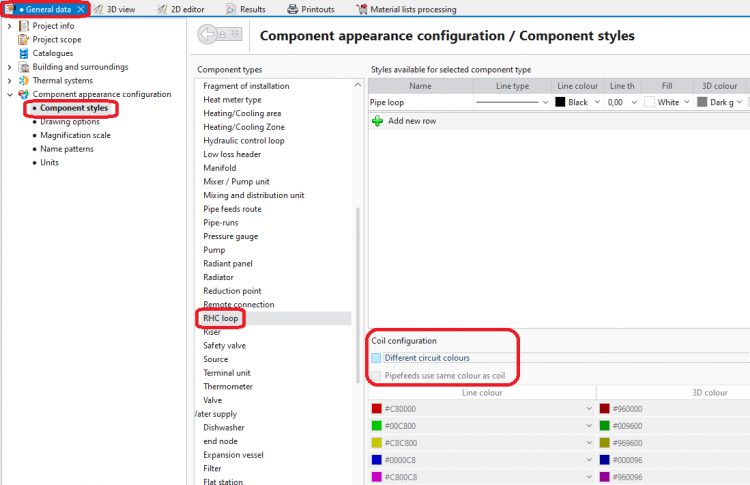
4. Component styles - no colour difference between loops 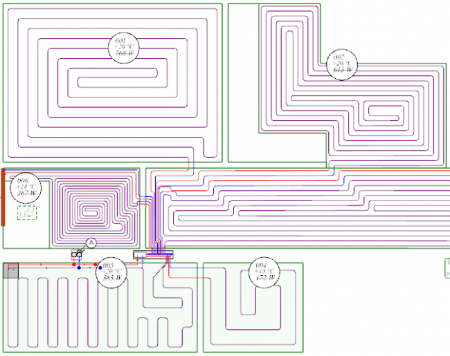
5. Graphical editing - no colour difference between loops 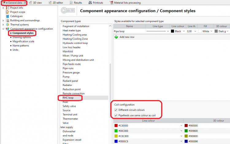
6. Component styles - loops differ in colour 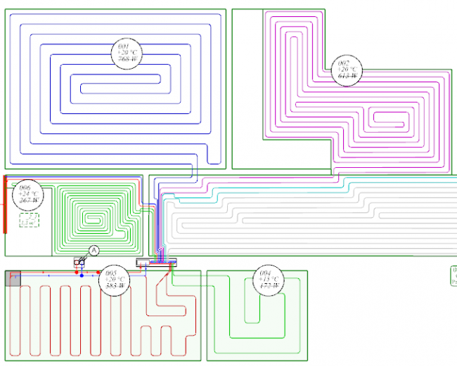
7. Graphical editing - loops differ in colour
- select manner of loop display where loops differ in colour and pipe feeds are of the same colour as the corresponding loops
- Rysunki pętli nie są obowiązkowe i nie muszą być kompletne, jeśli nie wybrano opcji "чертожна дължина на пръстен".
- W przypadku połączeń wirtualnych, automatycznie rysowane pętle wychodzą z punktów arbitralnie wybranych przez program. Po narysowaniu przyłączy lokalizacja punktów początkowych pętli zostanie automatycznie skorygowana. Zmianie mogą ulec również same rysunki pętli, wskutek uwzględnienia przebiegu przyłączy prowadzących do innych powierzchni/pomieszczeń.


