Подготовка конструкция на сграда
| Продукт | InstalSystem 5 |
| Вид статия | FUNCTION AND TOOL |
| Актуално съдържание за версия | IS 5.0 Beta Rev. 0.0.B33 |
Описание
Статията описва как конструкцията на сградата може да бъде подготвена и как може да бъде проверена създадената конструкция. Има няколко начина, по които конструкцията на сградата може да бъде подготвена за даден проект. Изборът на метода зависи от това кои данни от източника за структурата и етажни разпределения са налични и от обхвата на проекта, който трябва да бъде направен. Ако обхватът на проекта не включва изчисляване на топлинните загуби съгласно стандартите, тогава помещенията могат да бъдат представени в плановете като полигони без охлаждащи прегради. Всеки етаж представлява отделен графичен лист.
МЕСТОПОЛОЖЕНИЕ В ПРОГРАМАТА
Управление на етажи
- Управление на етажи е наличен в прозорец Общи данни.
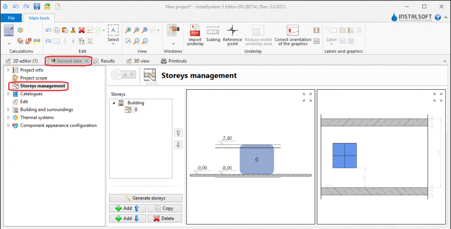
1. Управление на етажи

Внос на подложка
- Икони на елементи и функции, свързани с импортирането на подложки (чертежи за основи), се намират в прозореца "2D редактор" на лента Главни ленти с инструменти в секция Основа, когато Основа е разрешен обхватът за редактиране.

2. Import underlay

Сградна конструкция
- Икони на елементи и функции, свързани с импортирането на подложки (чертежи за основи), се намират в прозореца "2D редактор" на лента Главни ленти с инструменти в секция Конструкция, когато е разрешен обхватът за редактиране Конструкция.

3. Елементи на сградна конструкция

Изчисляване на сградна конструкция
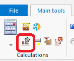
- Изчисление на сградна конструкция е налично в лента Главни ленти с инструменти на секция Изчисления.

4. Изчисление на сградна конструкция

Examples of use
Manual creation of building structure
Storeys
- Create the required storeys and append their data. The movie shows creation of two sets of storeys.
Underlay
Underlay (base drawing) is a two-dimensional (flat) graphical object retrieved from an external raster or vector file. The underlay itself does not provide building structure components, but it enables manual creation thereof adapted to the actual state of the building.
За повече информация, моля вижте: Import files
Помещение - ръчно създаване на помещения
- Create a Помещение manually using a contour line
or by drawing a diagonal line. When a room is created by drawing a diagonal line disable the ОРТО operating mode. After drawing the diagonal line complete the edition by right clicking.
Помещение - identification within area bordered with drawn partitions
Rooms can be created automatically in areas bounded by edges (surfaces) of the defined graphical partitions (walls, floor slabs, roofs). In this case it is necessary to draw graphical partitions in the project and to run Изчисление на сградна конструкция, which also enables adapting the partitions to the drawn plane of the roof.
- Place a series of Стена components by entering at the start the thickness of the wall in Таблица с данни and moving the cursor along the internal edges of the walls on the underlay. In underlays retrieved from a DWG file make use of the snapping to indicated layer feature. After placing Internal walls insert External walls in similar manner.
- Place the following components: Прозорец, Врата, Отвор в стена, Ниша.
- Place the following components: Плоча. Outline of one storey is by default covered by a single slab.
- Insert: Покрив.
- Create a multifaceted roof.
За повече информация, моля вижте: Preparation of building structure - Creation of roofs with different construction - Insert components Покривен прозорец
- Insert components: Отвор в плоча.
Отвор в плоча can be deleted by clicking
- Carry out Изчисление на сградна конструкция.
Изчисление на сградна конструкция launches a number of operations associated with providing a complete building structure:- cutting away partitions by the roof plane,
- automatic identification of rooms.
- Ponumerować pomieszczenia
- Nadanie symboli pomieszczeniom następuje poprzez wybranie operacji Номерирай помещения i zaznaczanie etykiet pomieszczeń w wybranej kolejności. Kolejność ta definiuje kolejność numeracji pomieszczeń
- Program pozwala na konfigurację schematu numerowania pomieszczeń
- Nadanie symboli pomieszczeniom następuje poprzez wybranie operacji Номерирай помещения i zaznaczanie etykiet pomieszczeń w wybranej kolejności. Kolejność ta definiuje kolejność numeracji pomieszczeń
Pokazana poniżej konfiguracja numeracji oznacza, że symbol pomieszczenia składa się z symbolu kondygnacji oraz kolejnego, zawsze dwucyfrowego, numeru na danej kondygnacji. Więcej objaśnień zostanie wyświetlonych po ustawieniu wskaźnika myszy nad ![]() .
.

Manual editing of rooms and automatic identification of walls and slabs against the background of underlay
The operation of automatic identification of walls and slabs enables creating these partitions within spaces identified between rooms included in the project and the outline of the building.
To carry out the operation:
- In the project file with previously inserted rooms, make a building outline using the 'Building outline' function.
- Optionally: if the building outline is identical on a number of storeys, enter appropriate values in the fields 'from storey' and 'to storey' in the data table of the building outline component.
- Launch interpretation of external and internal walls and slabs based on rooms and building outline using the Автоматични стени, плочи и покриви function.
5.Автоматични стени, плочи и покриви

Importing a complete building structure
Importing a building structure from a BIM (gbXML) compatible format
За повече информация, моля вижте: Import files
Importing a building structure from an InstalSystem 4 (ISB) project file
If necessary, manually correct or append the missing or incorrect components of the building structure thus obtained using the methods described above.
Verification of the correctness of building structure
Carry out the verification in the 3D изглед window
За повече информация, моля вижте: View navigation in the graphical editor