Този урок представя обща информация за работната среда на InstalSystem 5 и описва основните стъпки при проектиране чрез софтуера.
Модули и програмна конфигурация
InstalSystem 5 във всяка конфигурация
Интернет връзка
Стъпки на изпълнение
Подготовка на работната среда
Получаване на достъп до приложението
Необходимо е да имате достъп до инсталационния файл на програмата и до лицензионния номер, който е необходим за да активирате програмата на потребителския компютър. В случай на бета версия, моля свържете се с InstalSoft. След получаване на достъп към инсталационния файл, запишете го локално на Вашия твърд диск, след което стартирайте инсталацията.
Инсталация, активация, актуализация
Инсталация - За да преминете правилно през процедурата за инсталиране, моля следвайте помощните инструкции за инсталация. След като приключи инсталацията, приложението се управлява от InstalSystem 5 Manager, което е интегрална част от програмата. Следващата стъпка след инсталиране е активация. Преди инсталиране, моля убедете се че Вашия компютър изпълнява системните хардуерни изисквания, описани в: Техническа спецификация на пакета InstalSystem 5.
Активация - Това действие трябва да бъде изпълнено за да се използва програмата. Активацията се извършва чрез въвеждане на уникален ключ - лицензионния номер. Забележка: Активацията изисква Интернет връзка.
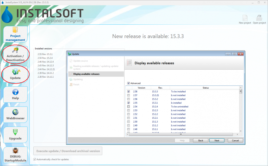
Актуализирай - Програмата се развива и актуализира постоянно. Промените се въвеждат в последващи издания на софтуерния пакет. Препоръчително е редовна актуализация на програмата през Интернет. Тази операция е безплатна и се извърша лесно посредством InstalSystem 5 Manager, което известява потребителя за налична нова версия. При актуализиране е възможно да изберете измежду редица издания на програмата, включително архивните. Множество издания могат да съществуват върху един компютър по едно и също време. При отваряне на файл, потребителят може да реши коя версия да използва. Информация за извършени промени в различните версии могат да бъдат видени в Бележки към издание InstalSystem 5. 1. Update
Софтуерна конфигурация
InstalSystem 5 се конфигурира на различни нива, които позволяват на потребителя да адаптира индивидуалните си нужди към приложението и да подобрява работния си комфорт:
Създаване на проектен файл и управление на проекти
Създаване на нов проект или отваряне на съществуващ проект
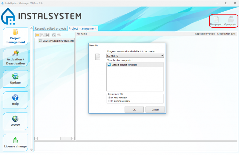
Нов файл - при отваряне на нов файл, можете да посочите шаблона, който ще бъде използван в проекта и да изберете такъв от изтеглени програмни ревизии за да работите с файла. Препоръчителна е употребата на последната версия на програмата.
Съществуващ файл - при отваряне на съществуващ проектен файл, можете да изберете програмна ревизия за по-нататъшна работа с файла. Това позволява работа с проекта чрез програмна ревизия, под която проекта е бил първоначално създаден. InstalSystem 5 съща така чете създадени с InstalSystem 4. 7. New file
Управление на проектни файлове и допълнителни файлове
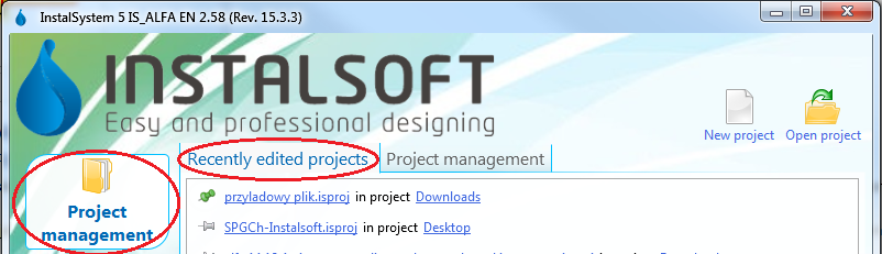
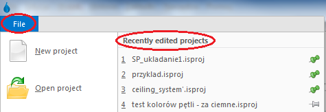
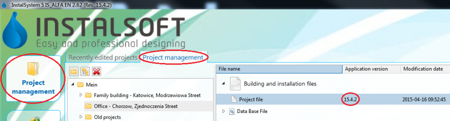
Наскоро редактирани проекти - този списък се създава автоматично и улеснява достъпа до проекти, които са били наскоро редактирани, независимо от тяхното местоположение. Те са достъпни както от Manager: 8. Recently edited projects , така и от меню Файл в прозореца InstalSystem редактор. 9. Recently edited projects Има опция за избор на проекти, които винаги ще се показват в горната част на списъка, без значение кога са изпълнени. Това става чрез използване на tacks - просто кликнете в/у кабърчето до избрания проект и ще се премести в горната част на списъка и ще остане там постоянно .
Управление на проекта - През време на инсталиране на програмата е възможно да се зададе стандартното местоположение на проектите. Това местоположение и всички негови под папки и файлове са достъпни от раздела Project management в прозореца InstalSystem Manager. Препоръчително е да създадете отделна подпапка за всеки проект (проектна структура / система) и да запазите там индивидуални версии на проекта InstalSystem (.isproj разширение) и други допълнителни файлове, напр. базови конструктивни чертожни файлове. Допълнително предимство е, че файловете във формат .isproj се показват, използвайки версията на софтуера, с която е разработен проектът. 10. Project management
Работа с проекта
Общи данни
В първия етап от работата с проекта са зададени общите данни и се проверяват настройките по подразбиране, които се използват в целия проект. Тези данни могат да бъдат променяни на всеки етап от разработването на проекта. Прозорецът General data е достъпен в списъка с прозорци, намиращи се в лентата с инструменти. Подробна информация относно основния обхват на General data, който трябва да бъде редактиран в зависимост от вида на проектираната система или извършеното изчисление, е даден в секции, описващи съответните приложения на софтуера - моля вижте:SOFTWARE APPLICATIONS.
11. General data
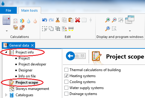
Проектна информация и обхват на проекта - дават възможност за добавяне на информация за проекта и избор на подходящ обхват за разработвания проект. 12. Project info and project scope
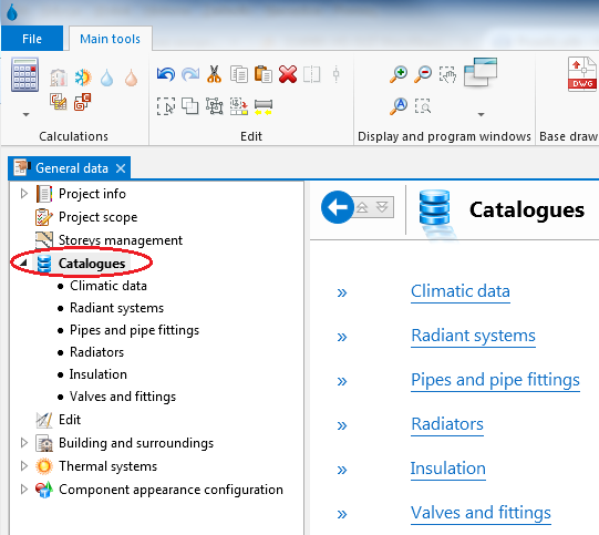
Каталози - наличните в програмата каталози са във формат на файлове, които не могат да се редактират с данни за елементи, които могат да се използват при проектирането на система. Специален тип каталози са за климатичните данни. Данните, съхранявани в каталозите, задържат потребителя да въведе многобройни подробни данни за елементите, използвани в проекта. Достатъчно е да се посочи продуктът или системата, които ще се използват в проекта, и програмата ще прочете всички необходими подробности от каталога. На този етап по принцип може да бъде определен набор от каталози за проекта. Продуктите от този каталог ще бъдат достъпни при редактиране на система или при избиране на елементи и провеждане на изчисления. В зависимост от конфигурацията на софтуерния пакет ще бъдат налични различни типове и разнообразни каталози. Каталозите могат да съдържат данни за общи елементи или елементи от определен производител. 13. Catalogues
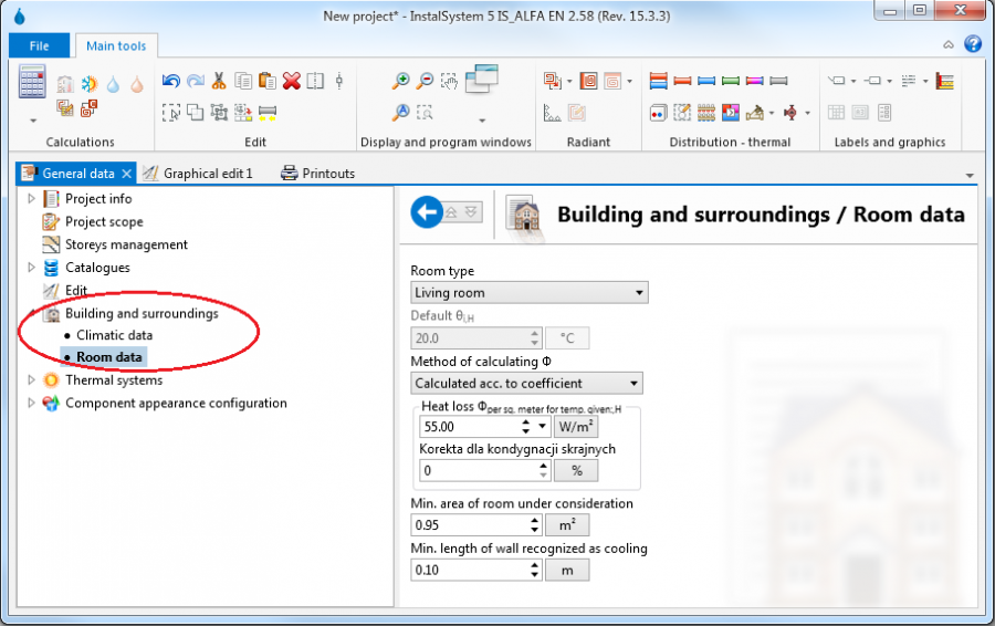
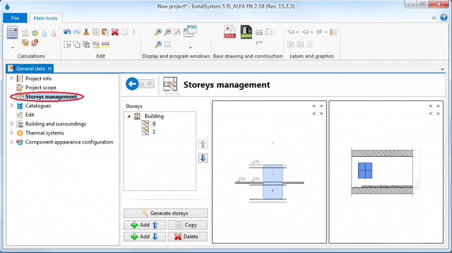
Данни на сграда - позволяват дефиниране на основни данни за сграда в контекста на проектираните системи. Building and surroundings обхваща информация за местоположението на сградата и данните за елементите на сградната структура по подразбиране, напр. необходимите показатели на мощност за отопление или охлаждане. 14. Building and surroundings Storeys позволяват дефиниране или промяна на структурата на сградата (брой на етажите и основни данни за тях). За всеки етаж се създава автоматично отделен лист, който позволява работа с плана на този етаж. 15. Storeys management
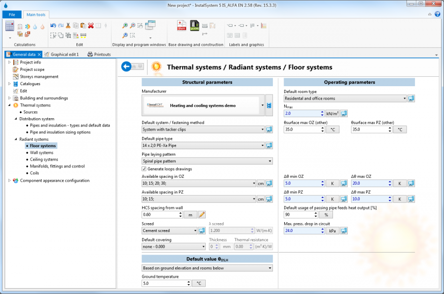
Данни по подразбиране на проектирани системи - тези данни се прехвърлят на всички системни елементи, които имат (символ)по подразбиране посочени в техните специфични полета. Ново добавените елементи имат това състояние. Стойността по подразбиране може да бъде променяна по всяко време - отделните елементи могат да имат своите данни или директно зададени от потребителя, или настройката "по подразбиране" може да бъде възстановена. "Общите данни" са достъпни в прозореца "Общи данни" под формата на няколко набора, определени за отделни секции на проекта, напр. "Топлинни системи". 16. Default data for floor heating systems
Конфигурация на външния вид на елемента и конфигурация на параметрите за редактиране - появата на елементите (например по отношение на цвят или мащаб) и някои параметри за редактиране могат да бъдат конфигурирани за всеки отделен проект. Това позволява по-добро адаптиране на външния вид на чертежите и начина на работа към индивидуалните изисквания на разработвания проект. Ако потребителят желае да приложи тези модифицирани настройки към други проекти, файлът с тези модифицирани настройки може да бъде записан като нов шаблон - моля, вижте:#Configuration point 3. Template files in Configuration 17. Component appearance
Основни елементи на среда за графично редактиране
Основните места, където се редактират данните за проекта, са прозорците Графична редакция и Таблица с данни . Как да отворите или да промените местоположението на тези прозорци в екрана е описано в: #Configuration Configuration, 2. point. Най - важните функции са достъпни чрез лента Основни инструменти и чрез изскачащото меню, което се показва след натискане на десния бутон на мишката. Изскачащото меню е зависимо от контекста - наличието и съдържанието му зависят от местоположението на екрана или обекта.
18. Basic of graphic editing
Графична редакция - графичният прозорец за редактиране позволява извършването на всички операции по редактиране на елементите, които съставят структурата на сградата или проектираните системи. Възможно е да се използват два отделни прозореца за редактиране на графики едновременно, като всеки от тях показва различна част от проекта. Най-важните елементи на този прозорец са следните:
Чертожни листове - графичният прозорец за редактиране показва един, текущо избран лист за рисуване. Проектът може да съдържа много листове за рисуване, всеки от които обикновено е причислен към друга сграда - вижте:#Setting_up_the_building_structure SETTING UP THE BUILDING STRUCTURE. Активният чертожен лист може да бъде променен от списъка с избора в горния ляв ъгъл на прозореца за редактиране Файл:Drawing-sheets-png.png
Редактирай раздели - това са слоевете на чертожния лист. В зависимост от активния раздел, специфичните елементи на проекта могат да бъдат редактирани. Някои елементи могат да бъдат редактирани на повече от един раздел. Съдържанието на лентата с инструменти също зависи от активния раздел. Независимо дали се показва или не табло (и следователно чертожните елементи, които са му определени), може да се конфигурира. Наличните опции се показват, когато кликнете с десния бутон на етикета на раздела. Символът, поставен вляво от етикета на раздел, показва текущата настройка на състоянието му за показване / скриване
Работни режими - се прилагат за редактиране на структурата на сградата или на която и да е система. Режимите могат да бъдат активирани / деактивирани в долния десен ъгъл на графичния прозорец за редактиране Файл:Auto-orto.png
ОРТО - Режимът ОРТО позволява поддържане на правилен ъгъл при редактиране, което позволява вмъкване на линии, разположени под прав ъгъл спрямо осите на координатната система. Натискането и задържането на клавиша Ctrl временно активира / деактивира режима ОРТО, който е много удобен при някои операции по редактиране.
МРЕЖА - Режимът GRID поддържа ръчно подреждане на тръбопровода и изчертаване на линия в рамките на отоплителна / охладителна зона.
АВТО' - Режимът АВТО активира автоматичното прихващане, което привлича компоненти до точки на възможна връзка или извършва други автоматични операции по време на редактирането, в зависимост от вида вложен или редактиран компонент и от околността му. Натискането и задържането на клавиша "Shift" временно активира / деактивира режима АВТО, което е много удобно при някои операции по редактиране.
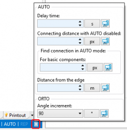
Прозорецът за настройка на операционните параметри на режими АВТО и АВТО - позволява да се регулират тези режими според индивидуалните изисквания. Прозорецът може да се покаже в долния десен ъгъл на графичния прозорец за редактиране.
Целият проект може да бъде визуализиран чрез натискане на бутон в долния десен ъгъл на графичния прозорец за редактиране.
Бутонът в долния ляв ъгъл на графичния прозорец за редактиране позволява промяна на скалата за показване на плана.
Таблица с данни - данните за текущо избрания елемент или обект са налични в таблицата с данни. Ако са избрани множество елементи от един и същ тип, в таблицата с данни ще бъдат показани полетата за данни, общи за всички тези елементи, което позволява едновременна промяна на избраните данни на множество елементи.
Основни инструменти - лентата с инструменти с най-важните инструменти, функции и компонентни икони, използвани за редактиране. Съдържанието на лентата с инструменти, независимо дали се показват или скриват пълните секции и дали отделните икони са активни или неактивни, зависи от контекста - активен прозорец и от прозореца Графичен редактор - активен. Когато курсорът на мишката се позиционира над избраната икона, се появява подсказка. Това помага да се запознаете със съдържанието на лентата с инструменти.
СекцияРедактирай осигурява общи функции за редактиране и функционалност за отмяна / ремонт на няколко нива.
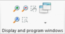
СекцияПокажи програмни прозорци осигурява инструменти за манипулиране на показването на проекта в графичния прозорец за редактиране.
Намали и Увеличи командите за показване на проекта, в допълнение към иконите в този раздел, също са достъпни чрез колелцето на мишката.
Премести показваният проект, в допълнение към иконата, също е достъпен чрез натискане и завъртане на колелото на мишката.
Покажи всичко в допълнение към иконата, също е достъпен чрез натискане на клавиша F5.
Setting up the building structure
The building structure forms a base for creating the system design. The building may consist of several storeys. A separate drawing sheet in the form of a plan is created automatically for every storey. In that sheet components of the building structure and of the system under design within that storey can be edited. The individual domains of the project are edited on separate tabs (layers), whereas the entire building and all of its systems designed form one consistent and integrated project. There are several methods of preparing the building structure for the design. Selection of the method depends on the available source data on the structure and plans of the storeys and on the scope of the design to be developed.
Import complete building structure - the best solution is to import data from a gbXML file. To make such an import the Base tab should be selected and the building icon, on the toolbar should be clicked to run the import function. After indicating the file to be imported, the process proceeds automatically. When importing from a gbXML file, both the structure of the storey referred to when discussing general data, as well as building components that form the plans of the individual storeys are imported.
Import plan views of individual storeys - may significantly improve work efficiency when files with drawings of the individual storeys of the building are available. In such case first the building structure must be defined in the Storeys section of General data. Then the plan views of the individual storeys should be imported from files in one of the supported formats, for instance: DWG, DXF, PDF, BMP, JPG and many other. Particularly useful is the import of the base drawing in the DWG format, as this makes the snapping function available when editing the structure. To import the base drawing the Base tab should be selected and then the "Drawing/base" component inserted into the project. Upon inserting that component, its data available in the Data table should be accessed and the file to be imported should be indicated in the Graphic file field. If printed plan view drawings are available, these can be scanned or photographed and the obtained file imported. 19. Import base The scale of the imported drawing should be specified by selecting the appropriate unit in the "Unit of measure in drawing" field in the Data table. After importing and scaling of all storeys the alignment of the drawings should be verified. To correct the alignment the Reference point component may be used. Then the required building structure components should be placed on the Structure tab, as described below in the Manual structure edit section, whereas the loaded base drawings form a background which facilitates structure editing.
Manual structure edit - the program enables drawing the required components of the building structure, rooms in particular, which will form basis for further design. Also in this case the building structure must first be defined in the Storeys section of General data. To define the area occupied by a room the Room function should be selected on the toolbar in the Structure tab. In this manner the areas of all rooms can be defined. 20. Room
Verification of the correctness of building structure
After defining the structure of the building it is advisable to verify the data that have been entered using the 3D view. The 3D view window is accessible in the list of windows located on the toolbar. The 3D view can be rotated in every direction which enables data verification using views from different sides and at different angles. The 3D view is controlled by means of a cube in the upper right corner of this window or by button ctrl and middle mouse button ("scroll") combination.
21. Building structure
Installation edit
The basic way to enter data of the system under design in InstalSystem 5 is graphical editing. Designing consists in placing objects (installation components) in the drawing and making appropriate connections between them. Work is done on plan views of the building storeys. The installation thus created can then be modified in any way, its fragments can be copied, and other operations can be made on it.
The software package offers a number of functions that support graphical editing, reduce the scope and time of necessary manual operations at this stage of design. Some components may be inserted or generated automatically. It is also possible to insert and edit groups of components.
There is a range of predefined graphical objects that can be used in the project. Examples: Project table, where designer data can be entered and which can be used when printing the project, or interactive elements, such as Manifold table and Component labels. Upon assigning them to defined system components, they will automatically display current data of these components.
It is particularly straightforward and problem-free to make all kinds of modifications to the project - the ergonomics and ease of calculation of the modified design is one of the biggest advantages of the working environment of InstalSystem 5. Файл:Graphical-edit.png22. Installation edit
Detailed information on Installation edit, in the context of the type of system being designed or calculations performed is given in the descriptions of program applications - see:SOFTWARE APPLICATIONS.
Verification of the correctness of installation structure
Before detailed component data are appended it is a good idea to check the structure of the system and component connections. Corrections made to the structure may cause changes or even removal of some of the components, then the time spent on entering data would be lost. The following tools are available:
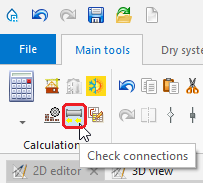
The tool that enables checking connections between system components in the project is the Check connections function, which is also available through the keyboard shortcut Shift+F2. 23. "Check connections" function
The tool that enables visual verification of the installation structure is, as is the case with building structure verification, the 3D view. The 3D view can be enabled permanently, which allows verifying system correctness continuously during editing. In this case it is particularly advantageous to work using two display monitors simultaneously. Note, however, that using 3D view slows down the program. When working on a slow computer or working with a large project, it is better to enable 3D view only to verify the status of the project, and to do the design work without opening the 3D view window. Файл:Installation-project.png24. Installation structure
Component data edit
Every component in the project has its set of data. Editing these data is possible in the Data table after marking that component. This applies to components of the building structure, components of all systems under design, and other components that are objects of the program, such as the "Graphical file" mentioned when discussing the import of storey plan views or the "Print layout". The Data table can be toggled on/off by selecting it in the Window menu on the toolbar.
A significant portion of the data of new components placed in the drawing is appended automatically. This highly facilitates work on the project. The range of automatically appended data differs depending on the type of component and on other factors.
The basic mechanism in this area is propagation of General data
Some data are established based on component location and size / shape of component placed in the drawing
Many detailed data of components that are associated with catalogue data and have a specified catalogue type are read from the catalogue.
Any default data can be overwritten with other data at any time. Information on whether the current value is derived from the "General data" or is another type of default data, or whether it is a user-defined value, is in the form of an icon placed to the right of the data field in the Data table. Clicking this symbol changes the data status. In particular it enables reverting to the Default status.
A Computer symbol indicates a default value
A Pencil symbol indicates a user-specified value
Data of any component can be entered or modified at any moment when working with the project.
Component data can be edited right after placing the component in the project, and this is recommended for some components. This particularly applies to these components that do not depend on other drawing components and the number of which in the project is low.
In the case of components the number of which is high it is advisable to edit their data at one stage to take advantage of group editing. To this end it is necessary to press and hold the Ctrl key and click every component to be marked. After marking multiple components, the data fields common to all those marked components will be accessible in the Data table, and every change made to selected data will modify that data for all marked components. Therefore it is very useful to conduct group editing of data of components of the same type, e.g. of many rooms.
Calculations and diagnostics
Calculations include all operations necessary to obtain complete results: data propagation, component sizing, engineering calculations and automatic graphical editing. All data that have an effect on the selected scope of the project are taken into consideration: general data, building data, drawings of the system under design, parameters of components used to construct the system taken from catalogues. This means that the program automatically provides high level of completeness and consistency of data and results. This approach greatly facilitates reverting to any of the previous stages of editing - after changing selected data, calculations can be conducted again to obtain complete and current results. Ease of reverting provides great comfort and speed of work in the context of calculating various design options, taking into account the changing requirements of the project developer or changes in the structure of the building introduced during the design of the installation.
Starting calculations - the Calculation section of the Main tools bar contains tools that enable starting and managing calculations. Calculations can be made for the entire project or for selected scopes.
Diagnostics and error list - at the start data completeness and correctness is verified. Significant errors in the data result in error messages and halted calculations. If there are no significant errors, calculations are completed and the error list is filled with diagnostic messages. These messages provide information on errors that do not halt calculations and warnings and hints regarding the course of calculations and obtained results. The Errors window is accessible through the Display and program windows menu. Initially all messages are displayed in bold font. Double clicking on a message enables finding the components or data referred to in the message in all open windows, for instance: Graphical edit, Data table, Calculation results. After the first search the message is displayed in normal font, meaning that it has been "checked". The pop-up menu available after selecting the message and right clicking allows viewing all components which encountered a similar problem. The range of displayed groups of messages can be controlled using the Filters function.
Errors - messages of highest importance, displayed in uppercase. Critical errors halt calculations and must be eliminated. There are also errors that do not halt calculations, but nevertheless they must be closely analysed and rectified.
Warnings - messages of lesser importance than errors, displayed in lowercase letters and they do not block further calculations. Warnings are usually associated with data or results that are presumably incorrect, therefore it is always advisable to read the displayed warnings.
Hints - messages intended to remind of or draw attention to some data or results. 26. Error list
Calculation results - in the InstalSystem the entire project may have a "calculated" status or a "not calculated" status. First calculation run changes the project status into "calculated". Calculations have an effect on the information displayed in many windows of the application. Importantly, changes made in data after first calculations do not cause deletion of results, results of the last calculations are available. An appropriate message warns of such status of the project. The most important result components:
Tables and lists available in the Calculation results window. Файл:Calculation-results.png27. Calculation results
Components displayed in the project drawing in the Graphical edit window, for instance results displayed in component labels or graphical components drawn or modified during automatic edit operations.
Information available after completing calculations, but not displayed permanently, for instance detailed results available in Graphical edit in Hints appearing in the case of most components when cursor is placed over it. Файл:Pipe-run-results-hint.png28. Pipe-run hint
Detailed information on calculations and results in the context of the various types of systems is given in the descriptions of software applications - see:SOFTWARE APPLICATIONS
Preparation of drawings for export/printing
After making all the required changes to the project and completing calculations, project components that complement information provided in printouts can be entered into the project. These components have an informative nature, and they do not affect calculations. It is advisable to place them in the project at this stage only, as the iterative work with the project at the earlier stages may require modification also in this respect. Including them at the final stage of work may prove most efficient. Detailed information on the available types of components in the context of the various types of installations is given in the descriptions of software applications - see:SOFTWARE APPLICATIONS.
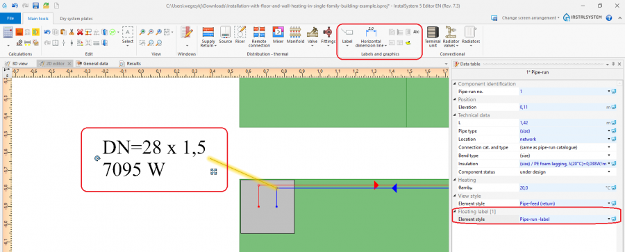
Example Component labels accessible through Main tool bar in the Labels and graphics section. A label is placed by selecting the appropriate icon in the toolbar and clicking the component to which the label is to be assigned. Upon marking in the drawing a component with a label, the label style can be selected in the Data table. 29. Component label The user can configure the label style - see section 5 Component appearance configuration and editing parameters configuration in General data. The user can create and save his/her own label styles of various configuration.
Export/print results and drawings
Result tables and drawings can readily be printed or exported in one of the many available formats.
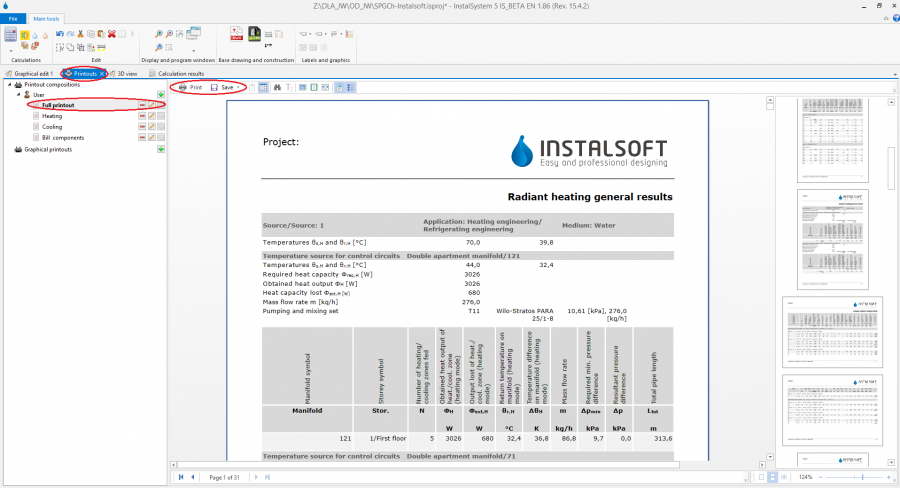
Print tables and lists - to print or export it is necessary to open the Printouts window. The tree displayed on the left side shows the available predefined printout compositions. The number and types of predefined proposals depend on the software version used. A composition can be selected and its content viewed. Then it is only necessary to select Print to obtain a printout or Save and, after selecting the target file format, export the results to this format. It is also possible to create and save user-defined printout compositions. These compositions, in addition to the predefined compositions, are then also available in other projects. 30. Print tables and lists
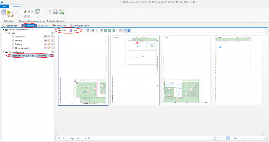
Print drawings - drawings are also printed and exported using the Printouts window. The tree displayed on the left side, below the table printout compositions, shows the graphical printouts defined for the project. The user can define many different layouts of graphical printout. For the defined layout, printing can be effected a number of times, e.g. after every project modification. The range of pages, its setup, style and other parameters are saved. This enables defining various printouts, e.g. one for exporting to a PDF file, another for sending to a printer, yet another for sending to a plotter. 31. Print drawings To set up a graphical printout layout it is necessary to:
Select Printouts tab in the Graphical editor window
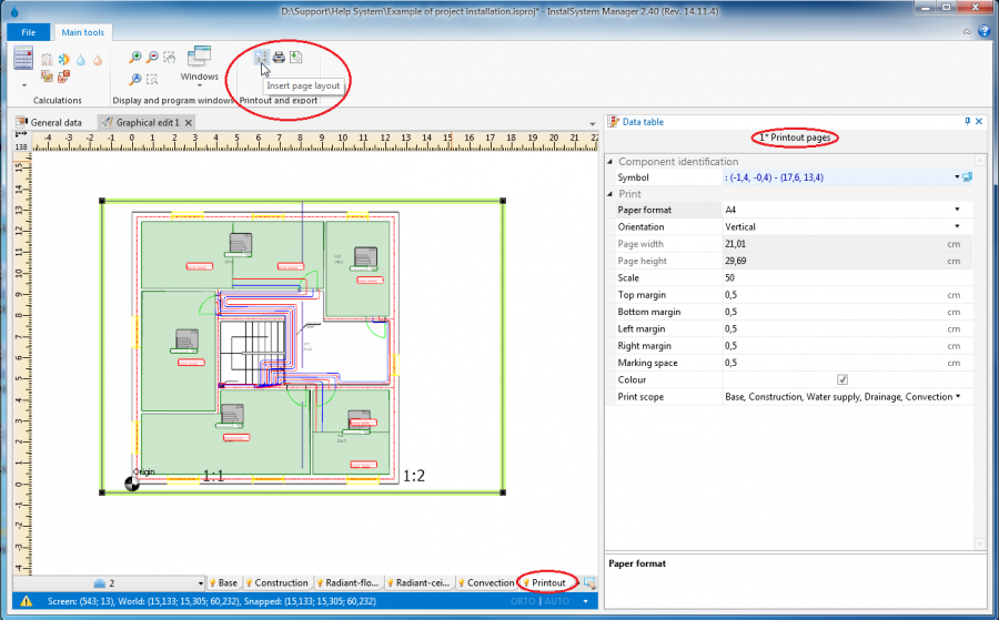
At Insetr page layout tool is available in the Printout and export section of the toolbar. This tool enables placing a Printout pages component in the drawing. To each Printout pages component placed in the drawing corresponds a separate graphical printout item in the Printouts window
The Printout pages component can be configured in the data table - a name should be assigned to it, its size, page layout and other style components can be modified
In the graphical edit area the outline of this component can be dragged by the mouse to an appropriate location in the project drawing. Its size can also be changed by dragging one of the corners, whereas the size is always a multiple of full pages. This way the area of the project to be printed can be marked. 32. Printout configuration


 до избрания проект и ще се премести в горната част на списъка и ще остане там постоянно
  .
.


 , on the toolbar should be clicked to run the import function. After indicating the file to be imported, the process proceeds automatically. When importing from a gbXML file, both the structure of the storey referred to when discussing general data, as well as building components that form the plans of the individual storeys are imported.
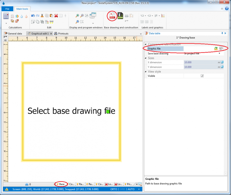
 component may be used. Then the required building structure components should be placed on the Structure tab, as described below in the Manual structure edit section, whereas the loaded base drawings form a background which facilitates structure editing.
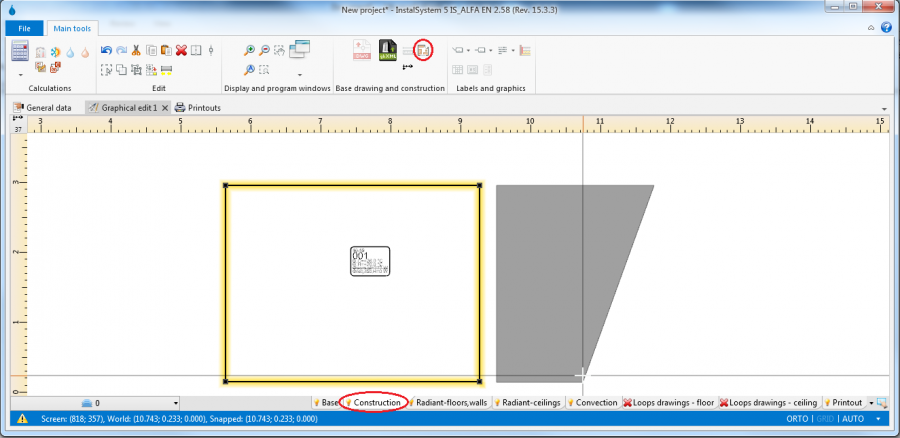


 - messages of highest importance, displayed in uppercase. Critical errors halt calculations and must be eliminated. There are also errors that do not halt calculations, but nevertheless they must be closely analysed and rectified.
 - messages of lesser importance than errors, displayed in lowercase letters and they do not block further calculations. Warnings are usually associated with data or results that are presumably incorrect, therefore it is always advisable to read the displayed warnings.
 - messages intended to remind of or draw attention to some data or results.
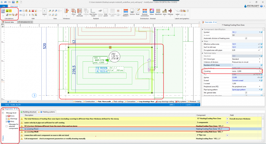


